
Versa Vision Measuring System User Guide: From Power-On and Setup to AI-Based Flying Measurement
Posted2026-8-20

Complete Operation Procedure and Precautions for Versa Series Image Measuring Instruments
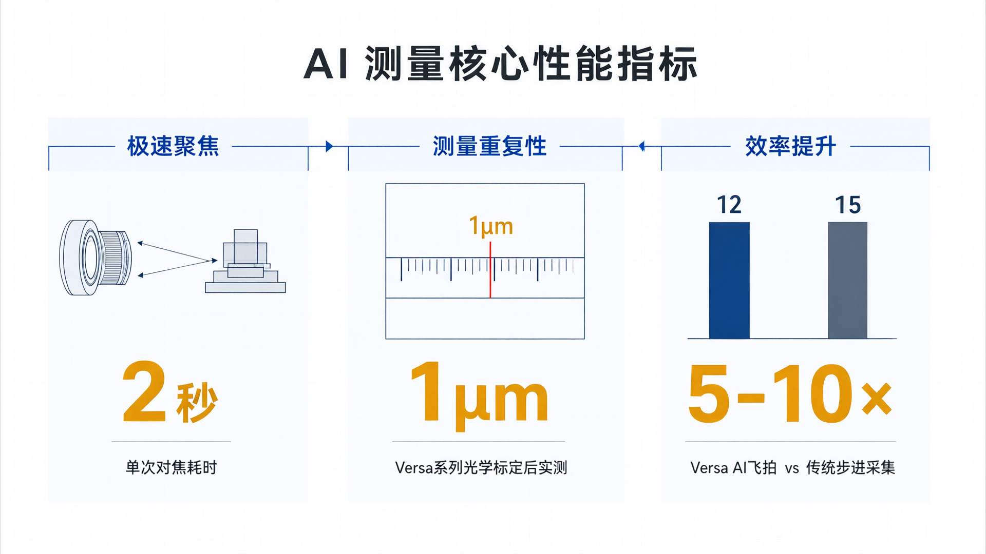
The measurement accuracy of vision measuring instruments largely depends on operational compliance. A device with a repeatability of 1μm can exhibit errors magnified several times if improperly clamped or lacking calibration procedures. Based on the technical characteristics of the Microtech Versa series vision measuring instrument, this article outlines key operational steps from startup to data output, helping users convert equipment performance into stable measurement results.
Power On and Environment Verification
The measurement accuracy of the Versa Series Vision Measuring System is sensitive to environmental conditions. Before powering on, verify these three baseline requirements: ambient temperature between 20 ± 2°C, relative humidity not exceeding 60%, and a vibration-free work surface. These parameters directly impact optical system stability and image acquisition quality.
Power-on sequence: Turn on the main power first, then the control cabinet, and finally start the computer to launch MicroCore Intelligent Measurement Software. During device initialization, the system automatically performs grating ruler zero calibration and lens distortion compensation. The process takes approximately 3 minutes. Do not move the measurement platform or touch the lens assembly during this time to avoid interfering with initialization.

Workpiece Fixturing and Coordinate System Setup
Workpiece fixturing is the most error-prone step in the measurement process. The Versa series features a high-precision granite worktable. During fixturing, ensure the workpiece datum surface is parallel to the table and secure it with dedicated fixtures to avoid deformation from excessive pressure. For thin-walled parts or flexible materials, vacuum suction is recommended to minimize mechanical stress.
Establishing the coordinate system is a critical step before measurement. In MicroCore, select "Coordinate System Setup" and align the coordinates by picking reference features on the workpiece (e.g., circles, lines, points). For batch inspection, use fixture locating blocks as a unified reference to reduce re-calibration time per setup. MicroCore's 2-second ultra-fast focusing feature quickly locks onto reference surfaces during this phase, boosting coordinate setup efficiency by approximately 5x.
Measurement Operations and AI Aerial Photography Applications
Once in the measurement phase, operators create inspection tasks and select relevant features (dimensions, angles, GD&T, etc.) in MicroCore software. The Versa series supports both contact probe and non-contact optical modes; for small parts like precision stampings or 3C electronic components, optical measurement is more efficient.
AI Fly-Shot is a core technology of the Versa series. Traditional image measuring instruments require a "move-stop-capture" cycle, whereas AI Fly-Shot achieves high-speed measurement during continuous motion through motion trajectory prediction and synchronized image acquisition. Once "AI Fly-Shot Mode" is enabled in MicroCore software, the device automatically traverses all measured features along an optimized path, improving measurement efficiency by 5-10 times compared to traditional modes. Users simply define measurement items in the task list; the system then generates the measurement path and executes it automatically.
For complex workpieces, use "Manual Mode" to select key features first, then leverage the "Auto-Learn" function to record measurement logic. Subsequent similar workpieces can directly call this program for batch execution. This workflow is ideal for high-frequency sampling scenarios such as semiconductor packaging and optical communication devices.
Data Processing and Report Generation
After measurement, MicroCore software automatically calculates actual values and deviations for each item, comparing them against preset tolerances. Out-of-tolerance items are highlighted in red to help operators quickly identify non-conforming features. Data can be exported to Excel, PDF, or CSV formats, or directly integrated with enterprise MES systems to close the quality data loop.
Report templates can be customized within the software, including company logos, part drawings, measurement data tables, and statistical charts. For test results requiring archiving, enable the "Digital Signature" feature to ensure report integrity and traceability.
Daily Maintenance and Accuracy Assurance
Long-term accuracy stability depends on strict adherence to maintenance specifications. After daily use, wipe the worktable and lens surfaces with a lint-free cloth to prevent dust accumulation that could degrade image quality. Inspect the grating scale readhead weekly for oil or grease; clean using a dedicated cleaner. Perform a full-system accuracy calibration monthly using standard gauge blocks or a calibration sphere to verify system errors. If deviations exceed allowable limits, contact MicroTech Support for recalibration.
MicroCore software includes built-in device health monitoring that displays real-time metrics such as scale status, lens contamination levels, and motion axis wear. When any metric approaches a threshold, the system proactively alerts for maintenance to prevent measurement inaccuracies caused by equipment degradation.
The core of operating the Versa series vision measuring system lies in "standardization." From environmental control and workpiece fixturing to measurement path planning and data output, the rigor at each step determines the reliability of the final results. While MicroCore software streamlines complex operations into standardized workflows, fully leveraging the equipment's performance still requires operators to remain focused and apply professional judgment at every stage.