
Precise Measurement of Product Outer Contours: Comprehensive Application of Vision Measuring Systems, CMMs, and Flash Measurement Systems
Posted2026-9-6
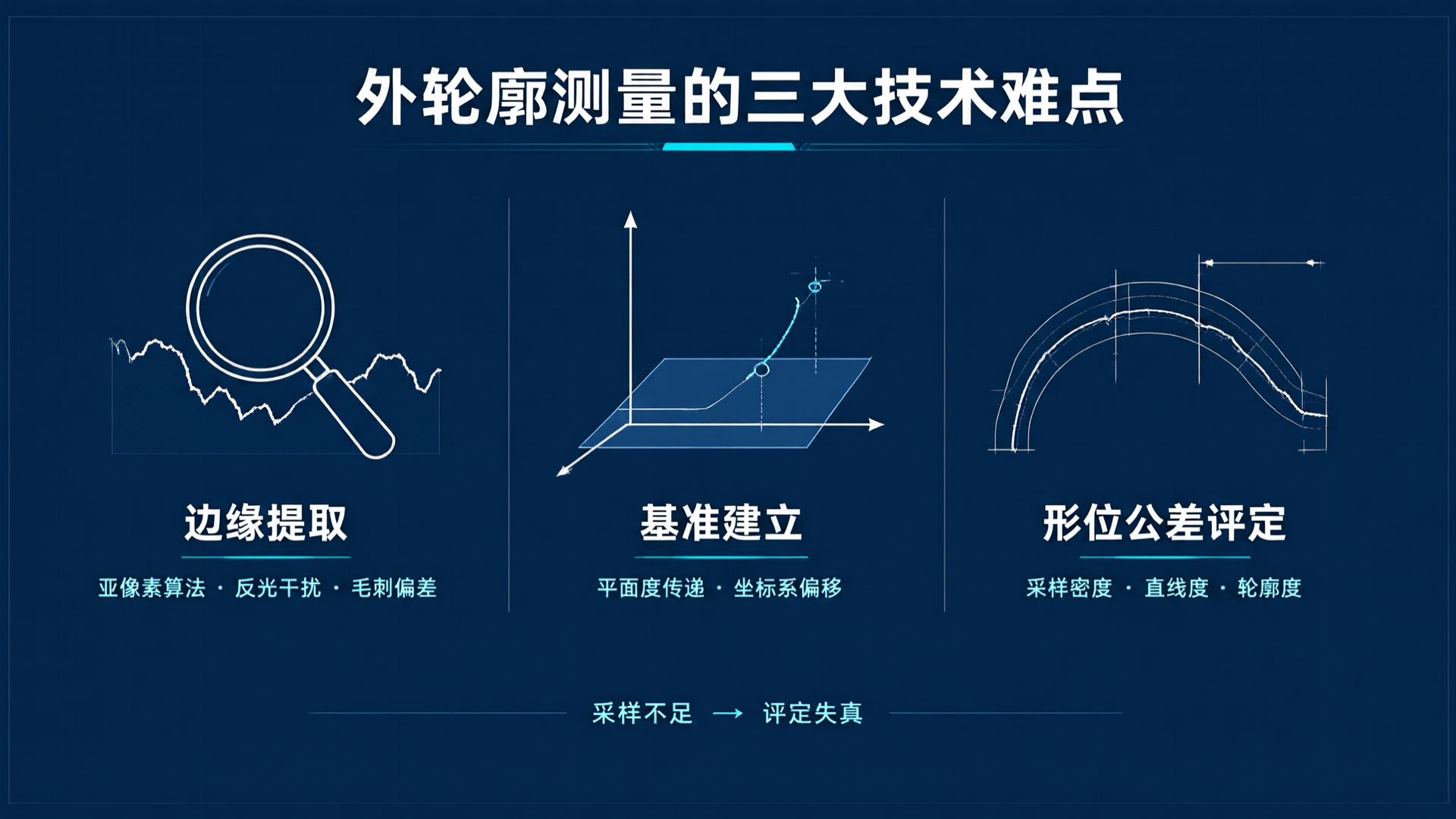
Measuring external product dimensions involves three key challenges: edge extraction, datum establishment, and geometric tolerance evaluation. Optical comparators, CMMs, and flash measurement systems each have distinct technical boundaries. This article analyzes how to design an inspection plan based on product characteristics across four dimensions: measurement principles, accuracy metrics, efficiency comparisons, and application scenarios.
In precision manufacturing, product outer contour dimensions are a core quality control metric. Whether it's connector terminals in 3C electronics with 0.1mm tolerances or the complex curved surfaces of automotive engine blocks, measurement accuracy directly determines assembly performance and product lifespan. For products varying by material, precision grade, and batch volume, a single measurement device often cannot meet all requirements. Vision measuring machines, coordinate measuring machines (CMMs), and flash measurement systems each have distinct technical boundaries. Understanding their operating principles and application scenarios is essential for developing an effective inspection strategy.
Challenges in Outer Contour Measurement: It's More Than Just "Measuring a Single Edge"
Measuring external contour dimensions is far more complex than it appears. What seems like a simple 2D outline actually involves multiple technical challenges.
Edge detection accuracy is the first critical hurdle. Optical imaging systems rely on CCD or CMOS sensors to capture contour images, using sub-pixel edge detection algorithms to determine boundary positions. When a product surface exhibits reflections, burrs, or chamfers, sharp variations in edge grayscale gradients can cause algorithmic deviations in identifying the "true" edge. Coordinate measuring machines (CMMs) use a probe for physical contact; errors arising from probe radius compensation and cosine errors relative to the touch direction similarly impact boundary positioning accuracy.
Establishing the datum is the second critical step. Outer contour dimensions are typically defined relative to a specific datum coordinate system. Any errors in the flatness of the datum plane or the position of datum holes will propagate into the contour measurement results. If the datum establishment is inaccurate, all subsequent dimension data will deviate from the true values.
The third challenge lies in evaluating geometric tolerances. The outer profile includes not only linear dimensions but also geometric tolerances such as straightness, roundness, and profile. Accurate evaluation of these parameters requires a sufficiently dense set of sampling points; insufficient sampling can lead to distorted results.
Vision Measuring System: The Primary Solution for Optical Non-Contact Measurement
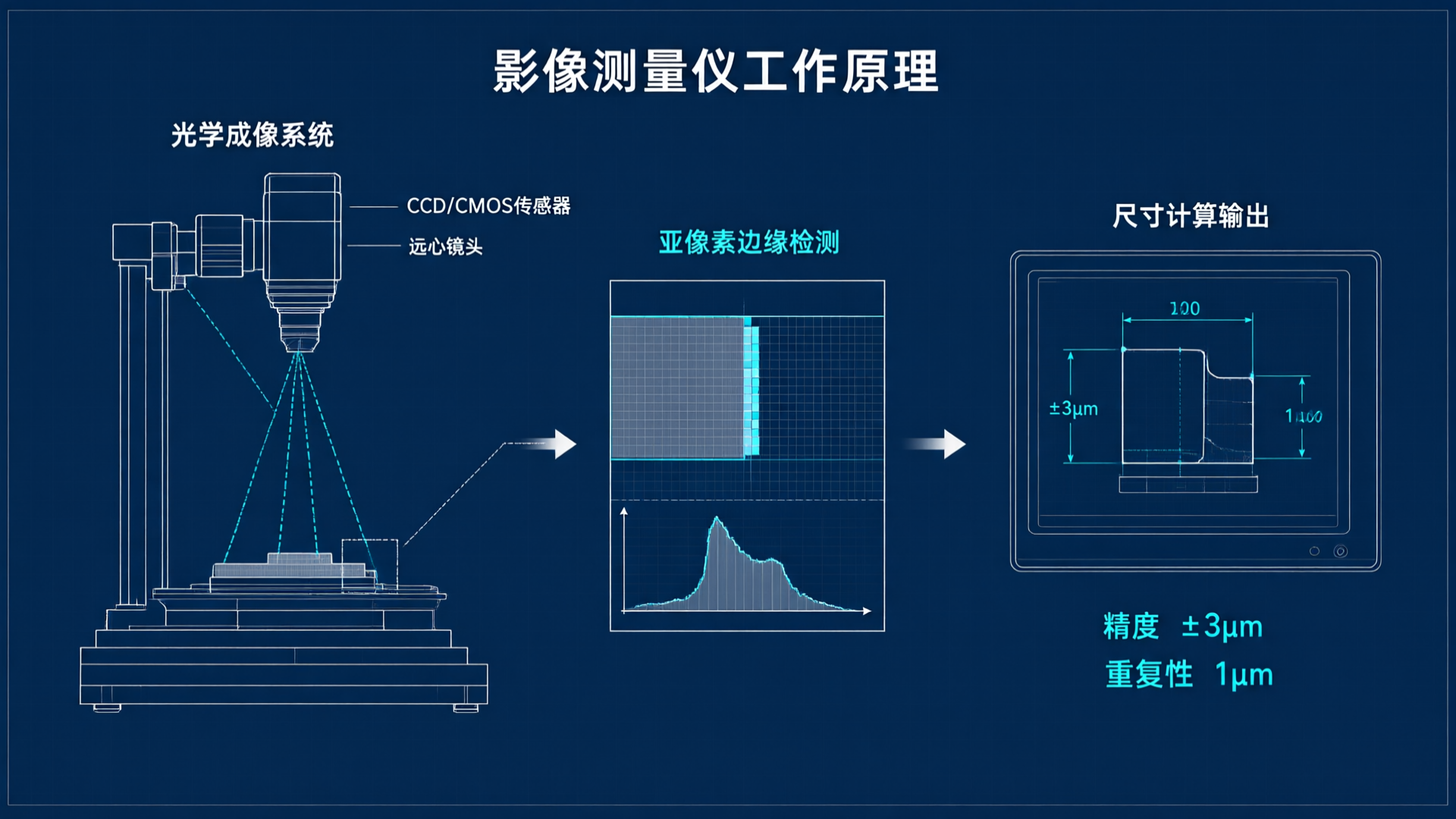
Image measuring instruments use optical imaging systems to magnify product contours and project them onto image sensors. Image processing algorithms then extract edge coordinates to calculate dimensional parameters. Their core advantages are non-contact measurement, high efficiency, and a large field of view.
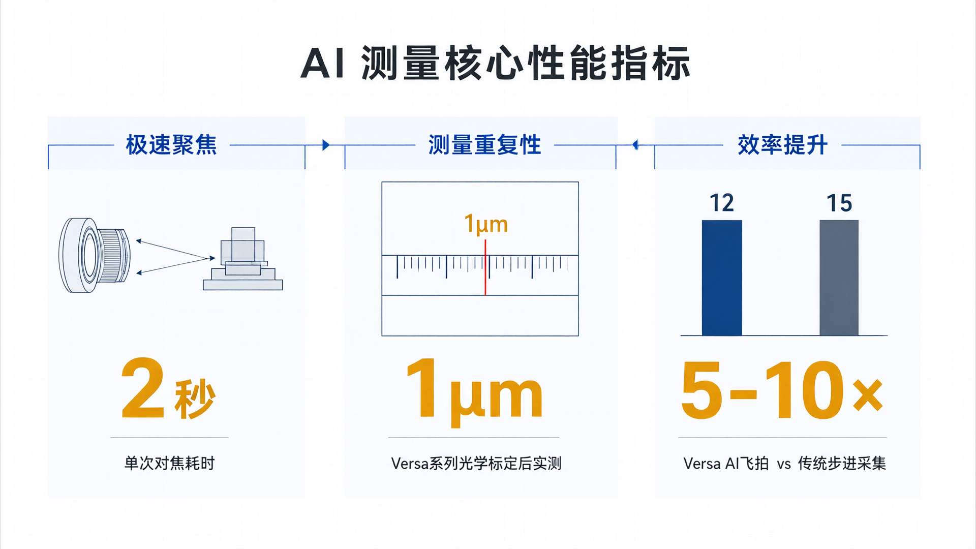
Based on measurement principles, optical comparators are categorized into contour projection and surface imaging methods. Contour projection projects a product's outline via parallel light onto a telecentric lens image plane, making it ideal for measuring thin-walled parts made of transparent or semi-transparent materials. Surface imaging directly captures the product surface, suited for outer contour inspection of opaque solids. The Makewise Versa series optical comparators utilize surface imaging and are equipped with MicroCore AI intelligent measurement software. By leveraging AI Fly-Shot technology, they enable continuous image capture and real-time measurement during motion, boosting single-part measurement efficiency by several times.
Typical accuracy specifications for vision measuring systems include a linear indication error within (3+L/200) μm (where L is the measured length in mm) and repeatability at the 1 μm level. This precision meets the requirements for contour inspection of most 3C electronics and precision stamping components.
The limitations of vision measuring systems are also clear. As fundamentally 2D measurement tools, they offer only limited height measurement capability—even with probes or laser sensors on high-end models—and struggle to profile complex 3D surfaces. Additionally, there is an inherent trade-off between field of view and resolution: a larger field of view reduces resolution, while higher resolution requires a smaller field of view. Select the appropriate magnification based on the size of the features being measured.
Coordinate Measuring Machine: The benchmark device for high-precision 3D contour inspection
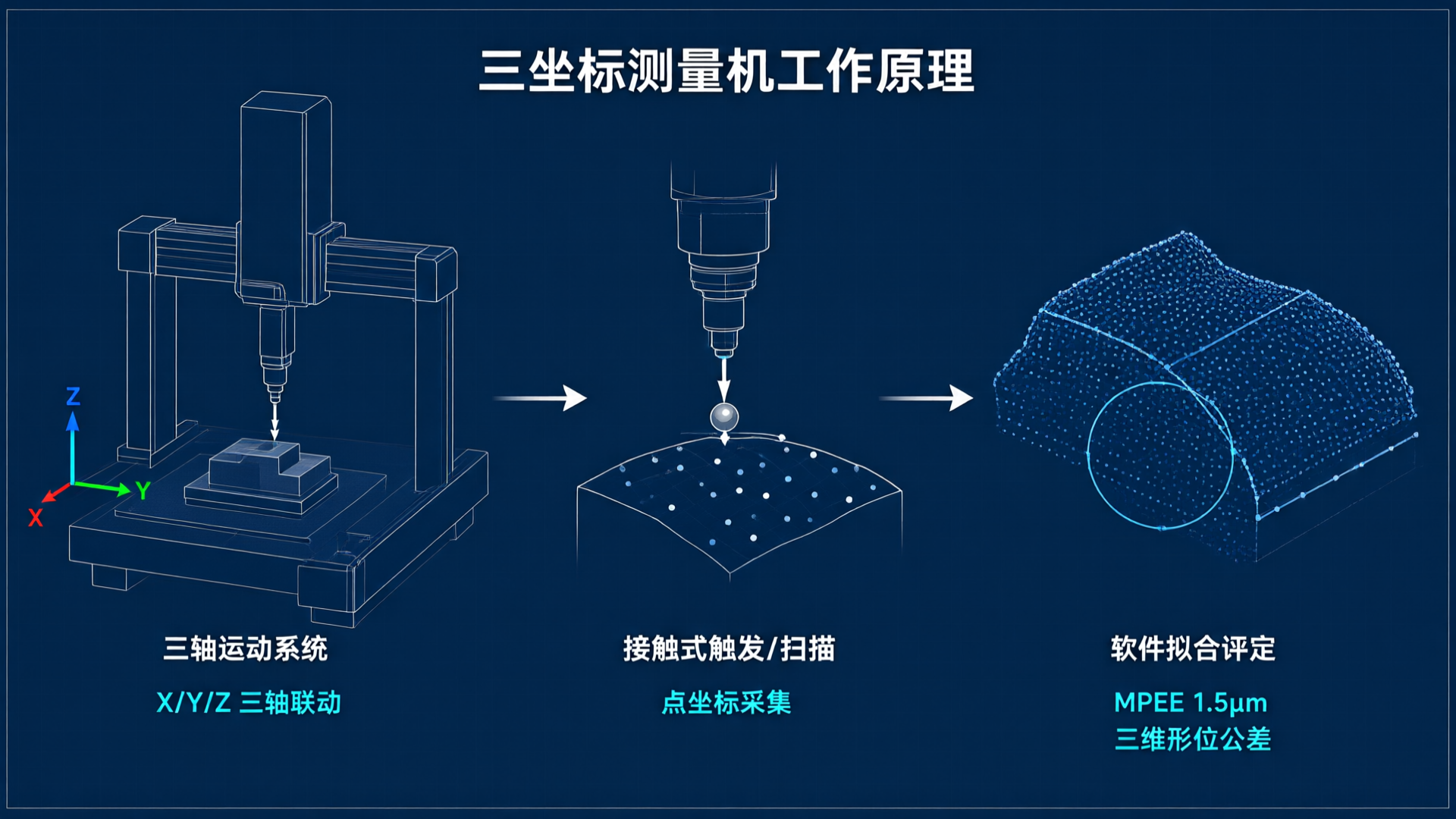
Coordinate Measuring Machines (CMMs) capture discrete point coordinates in 3D space using a probe system, then calculate geometric parameters via software fitting. As one of the highest-precision dimensional measurement tools available, CMMs are widely used for final inspection and metrology certification of precision components.
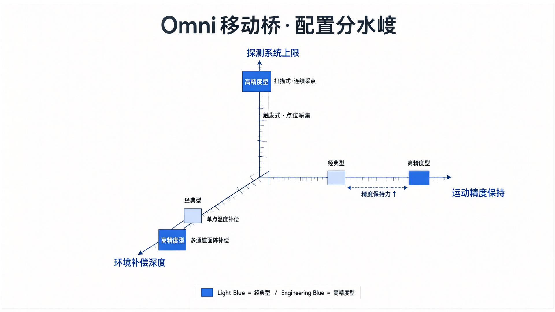
The core accuracy metric for Coordinate Measuring Machines (CMMs) is Maximum Permissible Error of Indication (MPEE), with high-precision models achieving 1.5μm. Probe systems are categorized into touch-trigger probes, scanning probes, and non-contact optical probes. Touch-trigger probes collect coordinates via single-point triggering, ideal for discrete point measurement. Scanning probes glide continuously over surfaces to capture dense point clouds, making them particularly effective for evaluating external contour form errors. The Maike Zhice Omni series CMMs offer classic moving bridge, high-precision moving bridge, and large-stroke high-precision moving bridge models to meet diverse part size requirements.
The unique value of CMMs in external contour measurement lies in three aspects. First, they capture 3D coordinate data simultaneously to comprehensively evaluate spatial orientation, flatness, cylindricity, and other 3D geometric tolerances. Second, the probe can extend into internal cavities and deep holes to measure hidden contour features that optical comparators cannot reach. Third, their measurement results are traceable to standards and can serve as authoritative evidence for dispute resolution.
The main limitation of coordinate measuring machines (CMMs) is measurement efficiency. Their point-by-point probing approach results in long cycle times per part, making them less cost-effective for high-volume full inspection. Additionally, measurement accuracy is sensitive to ambient temperature, vibrations, and probe calibration status, requiring strict environmental conditions.
Flash Tester: The Ultimate Tool for High-Speed Batch Inspection
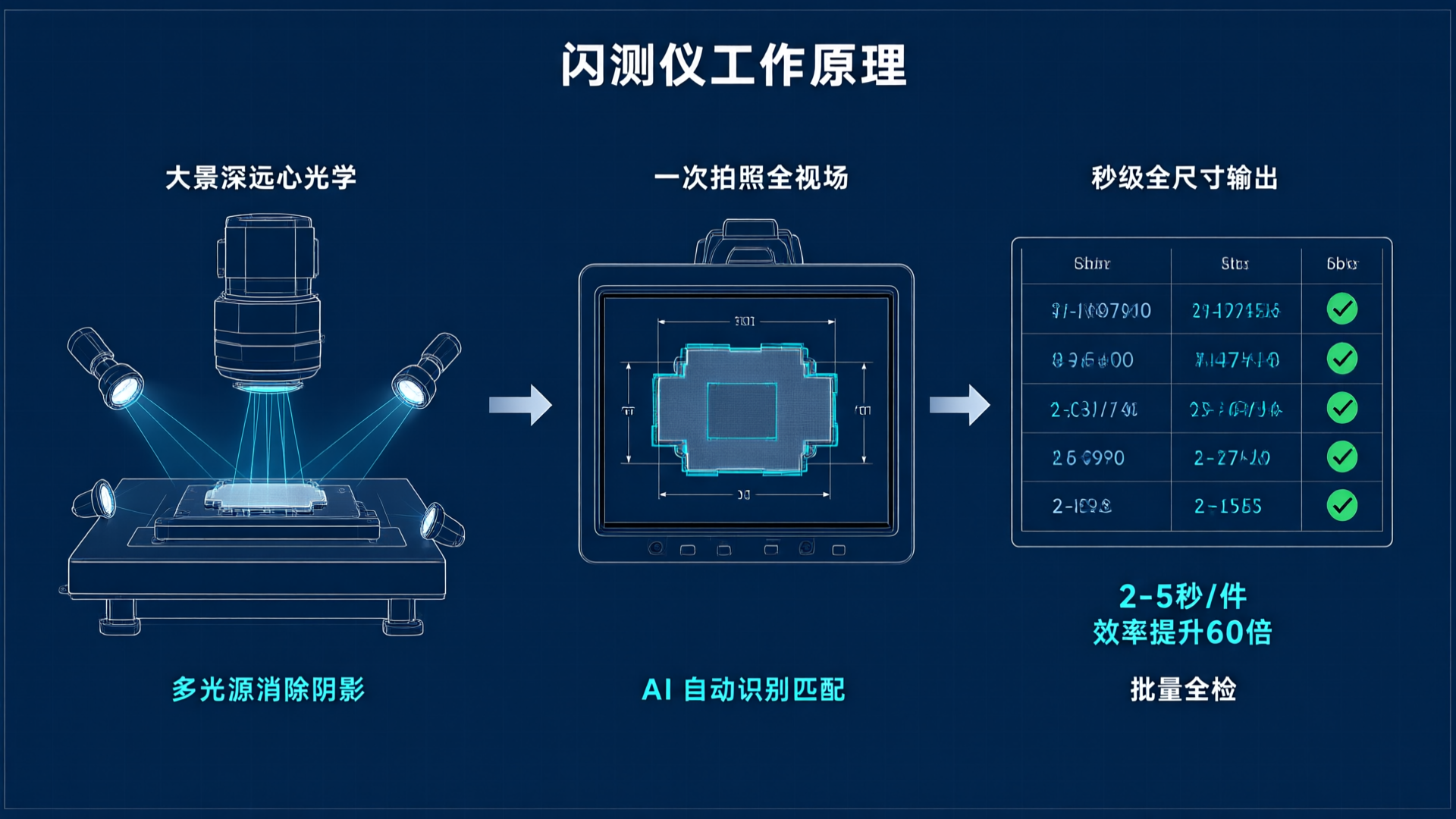
The FlashMeasurer (also known as the One-Touch Vision Measuring System) is a rapidly adopted measurement device. Its core design philosophy is simple: place the product on the stage, capture a single image, and instantly calculate all dimensions—reducing per-part measurement time to seconds.
The FlashMeasurer's technical foundation combines a large-depth-of-field telecentric optical system with a high-resolution area-scan sensor. Telecentric lenses eliminate perspective distortion, while dual or multi-side lighting sources remove shadow interference to capture clear contour images in a single exposure. The MicroCore AI software's auto-recognition and batch measurement features automatically match product models and invoke measurement programs, delivering a "place-and-measure" user experience.
The efficiency advantage of flash measurement systems is especially evident in high-volume inspection scenarios. Taking precision stamped parts as an example, a single product requires measurement of 20 external profile dimensions. Traditional vision systems measure element-by-element, taking approximately 3-5 minutes, while flash measurement captures all data in a single image, completing calculations in just 2-5 seconds—an efficiency gain of roughly 60 times. For production lines inspecting hundreds of thousands of units daily, flash measurement is often the only economically viable solution.
Flash measurement accuracy is typically ±(3+L/50) μm, slightly lower than high-end vision measuring machines and CMMs. This level of accuracy suits products with tolerances above 0.02mm, but sub-micron precision parts still require higher-accuracy equipment. Additionally, flash measurement range is limited by field of view; large parts require stitching measurements, which reduces efficiency advantages.
Comparison of Precision, Efficiency, and Use Cases Across Three Device Types
Comparing the three device types side by side makes their technical boundaries clearer.
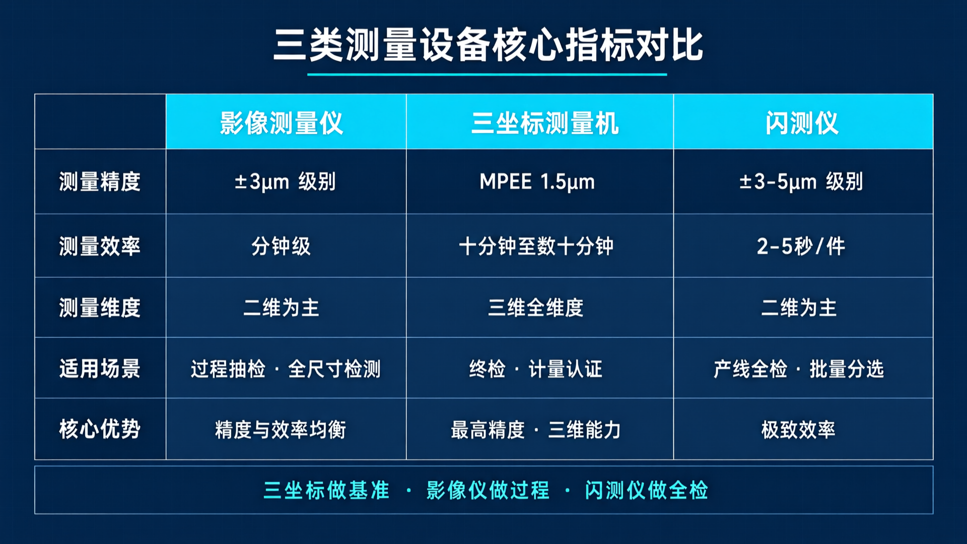
In terms of measurement accuracy, coordinate measuring machines (CMMs) rank highest (MPEE up to 1.5μm), vision measuring systems fall in the middle (indicative error around 3μm), and flash inspection systems are slightly lower (approximately 3-5μm). This difference in accuracy stems from their underlying measurement principles: contact-based spatial positioning is inherently more precise than optical pixel resolution.
In terms of measurement efficiency, flash measurement is fastest (completing full-size measurements in seconds), followed by vision measurement systems (taking minutes), while coordinate measuring machines (CMMs) are slowest (ranging from 10 to dozens of minutes). This efficiency gap stems from data acquisition methods: area sensors capture all pixel information at once, far outpacing point-by-point triggering or element-by-element programmed measurements.
In terms of application scenarios, the three device types complement each other. Coordinate Measuring Machines (CMMs) are ideal for high-precision final inspection, metrology certification, and complex 3D profile evaluation. Vision Measuring Systems suit medium-precision 2D full-dimension inspection and process sampling. Flash Inspection Systems excel in high-volume production line full inspection and rapid sorting. In practical quality assurance systems, all three often coexist: CMMs serve as the metrological benchmark for periodic sampling, vision systems handle daily process control, and flash inspection systems cover full-production line inspection requirements.
Comprehensive Application: Develop Inspection Plans Based on Product Features
When selecting measurement equipment, prioritize matching product characteristics and inspection requirements over seeking the highest accuracy. The following criteria can help users make an informed choice.
Tolerance grade is the primary criterion. When external contour tolerance is within 0.005mm, a CMM or high-precision vision measuring system should be prioritized. For tolerances between 0.005 and 0.0 mm, a vision measuring system offers the best cost-performance ratio. When tolerances exceed 0.02mm and batch sizes are large, flash measurement systems deliver the highest efficiency.
Contour complexity determines the required device dimension. All three device types can handle pure 2D contours (lengths, angles, and arc radii within a plane). However, when dealing with 3D spatial contours (surface profile and spatial position), the 3D data acquisition capability of coordinate measuring machines is irreplaceable.
Batch size impacts equipment selection economics. For low-volume, multi-variety production under 10,000 units annually, the flexible programming of video measuring systems is more suitable. For high-volume, single-variety production exceeding 100,000 units annually, flash measurement systems with second-level cycle times align better with line throughput. For medium-volume scenarios in between, a combined solution leveraging both technologies balances flexibility and efficiency.
Material and surface finish must also be considered. Highly reflective materials (e.g., polished stainless steel, anodized aluminum) can cause overexposure or edge blur in optical imaging; in such cases, contact CMMs provide more reliable results. Transparent or translucent materials (e.g., glass, acrylic) are best measured using profile projection vision measuring systems.
Conclusion
Precise measurement of a product's outer dimensions is fundamentally a balancing act among accuracy, efficiency, and cost. Coordinate Measuring Machines (CMMs) offer the highest accuracy and 3D capabilities; vision measuring instruments strike a balance between precision and speed; flash measurement systems deliver maximum efficiency for high-volume inspection. The technical boundaries of these three equipment types are well-defined, and they complement rather than replace one another in practical applications.
For manufacturing enterprises, a sound inspection system doesn't chase peak performance from a single device. Instead, it strategically deploys three equipment types across different stages of the quality process based on product tolerance grades, profile complexity, batch volume, and material characteristics: CMMs for reference measurements, vision systems for in-process checks, and flash measurement systems for full inspection. This layered approach ensures measurement reliability while controlling both inspection costs and cycle time. Meike ZhiCe's continued investment in the Versa Vision System, Omni CMM, and MicroCore AI Intelligent Measurement Software is designed to help enterprises achieve a seamless, consistent experience—from hardware to software—within this layered framework.