
Common Probe Types for Coordinate Measuring Machines: Selection Logic and Calibration Essentials
Posted2026-9-14
The measurement accuracy of a CMM largely depends on the proper configuration of its probe system. This article systematically outlines key engineering practices for CMM probe applications across four dimensions: probe type, material selection, selection principles, and calibration standards. It covers the applicable scenarios and selection logic for four common probe types: straight, star, disk, and cylindrical probes.
The measurement accuracy of a coordinate measuring machine (CMM) largely depends on the proper configuration of its probe system. As the physical interface between the probe head and the workpiece, the probe's type, material, and assembly directly impact the reliability of measurement results. This article systematically outlines key engineering practices for CMM probes across four dimensions: probe types, material selection, selection criteria, and calibration standards.
I. Four Common Probe Types and Their Application Scenarios
In coordinate measuring, four common probe types are used, each suited to specific measurement tasks and workpiece features.
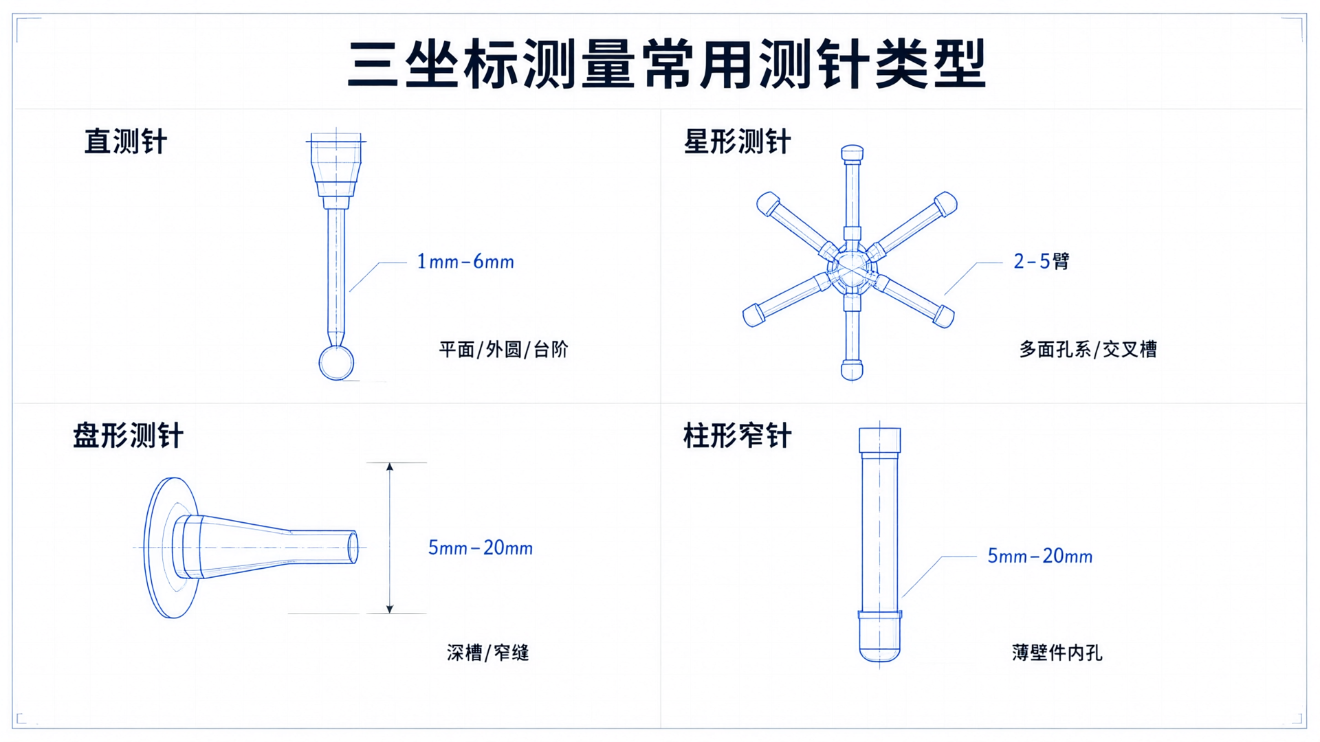
Direct Probe (Ball Probe)The most basic probe type, consisting of a probe stem and a spherical tip. Tip diameters typically range from 1mm to 6mm, making them suitable for most standard measurement tasks. With their simple structure and high rigidity, straight probes are the go-to choice for routine measurements. They provide stable contact and reliable repeatability when measuring flat surfaces, external cylinders, steps, and other regular geometric features.
Stylus probeConstructed from multiple straight probes arranged at specific angles, typically configured with 2 to 5 probe arms. The key advantage of a star probe is its ability to contact the workpiece surface from multiple directions without changing the probe head. This makes it ideal for measuring complex geometries, such as multi-face feature sets, intersecting slots, and irregular contours. When using a star probe, phase calibration for each probe arm must be performed in advance within the measurement software.
Disc-type probeThe tip of the probe has a disc shape, with diameters typically ranging from 5 mm to 20 mm. Disc probes are designed to measure features that straight probes cannot easily reach, such as deep grooves, narrow slots, and step sides. The disc edge forms a line contact with the workpiece surface, enabling measurement within confined spaces. Due to lower rigidity compared to straight probes of the same length, selecting a disc probe requires balancing reachability against rigidity.
Cylindrical probeCylindrical tip designed for measuring internal bores of thin-walled parts and narrow slot bottoms. The cylindrical surface ensures face contact with the workpiece, providing a larger contact area in specific directions. Typically paired with straight probes to form a complete measurement solution.
2. Material Selection for the Ball and Rod
The probe consists of a stylus tip and a stem; their material selection follows distinct engineering principles.
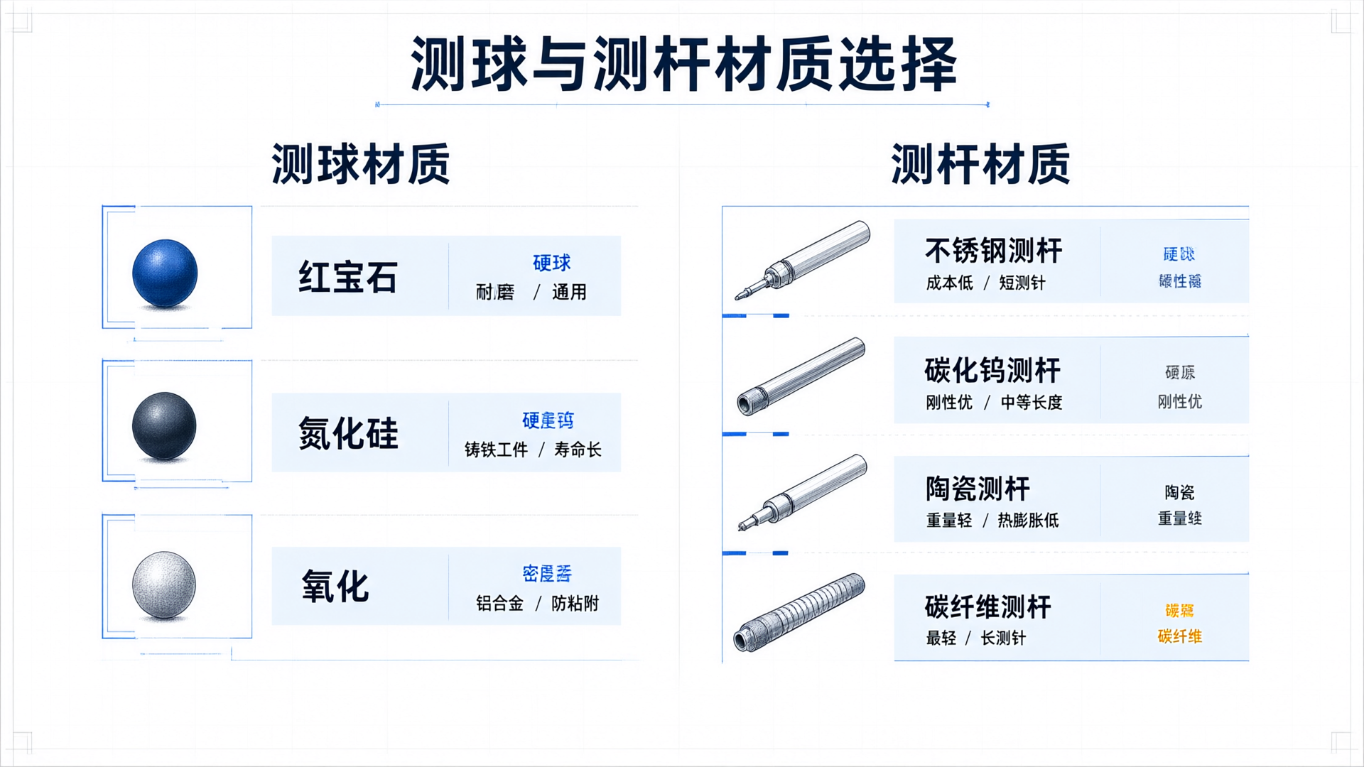
Regarding the material of the test ball,Ruby ball measurementThe most widely used choice. Ruby (single-crystal aluminum oxide) offers high hardness, excellent wear resistance, and low surface roughness, meeting the needs of most measurement scenarios.Silicon Nitride Probe BallHarder than ruby, offering superior wear resistance and longer service life when measuring hard workpieces such as cast iron.Zirconia Measuring BallDensity between the two, suitable for measuring soft materials like aluminum alloys to reduce material adhesion between the probe ball and the workpiece.
Regarding the material of the test rod,Stainless Steel Measuring RodLow cost and easy to machine; ideal for short probes and routine measurement tasks.Tungsten Carbide ProbeRigid probes outperform stainless steel with less deflection at the same length, making them ideal for medium-length probe configurations.Ceramic probeLow weight and low coefficient of thermal expansion, ideal for precision measurement applications requiring control of probe mass and temperature effects.Carbon fiber probeLightest weight, offering significant advantages in long probe configurations by effectively reducing inertial forces and deformation during probe movement.
Basic principles for probe selection: choose the shortest probe, largest stylus tip, and highest rigidity possible while ensuring reliable contact with the target feature.
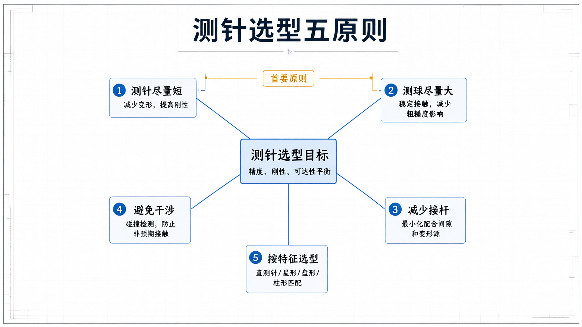
3. Five Engineering Principles for Probe Selection
Stylus selection is not a simple specification match; it is a systematic engineering process that comprehensively considers measurement tasks, workpiece characteristics, and equipment capabilities.
Keep the probe as short as possible.Rigidity is the primary concern. Increasing stylus length reduces rigidity, leading to greater deformation under measurement force and directly compromising accuracy. In engineering practice, stylus length should be kept as short as possible while still meeting reachability requirements.
Maximize the ball sizeThe principle is based on contact stability. A larger probe ball provides a more stable contact point and reduces the impact of surface roughness on measurement results. However, the probe ball diameter is constrained by the geometric dimensions of the feature being measured, requiring a balance between accessibility and stability.
Reduce unnecessary rod connectionsCritical for ensuring probe system rigidity. Each additional extension rod joint introduces extra fit clearance and deformation sources. During measurement planning, prioritize integrated probes or minimize the number of extension rods.
Avoid probe interferenceWhen planning measurement paths, ensure the probe does not unexpectedly contact the workpiece surface. Probe interference can cause abnormal measuring forces, stylus deflection, or even stylus damage. Use the collision detection feature in your measurement software to identify and eliminate interference risks during programming.
Select probe type based on featuresSelection logic is based on feature geometry: use straight probes for regular features, star probes for complex multi-faceted features, disk probes for deep slots and narrow gaps, and cylindrical probes for special scenarios. No single probe can cover all measurement tasks; the probe configuration must be tailored to the specific workpiece features.
IV. Key Control Points for Probe Calibration
Stylus probes require regular calibration before and during use to eliminate the impact of manufacturing errors and installation deviations on measurement results.
The core purpose of probe calibration is to determine the effective diameter of the probe tip and its positional relationship. The calibration process uses a standard sphere as a reference, calculating the actual diameter and center position of the probe tip through multi-point contact measurements. Calibration results directly impact the accuracy of subsequent measurements.
Key parameters must be controlled during calibration. The precision grade of the reference sphere should match the measurement task; typically, select a sphere with a precision grade one order of magnitude higher than that required for the workpiece. Maintain the calibration measuring force consistent with actual measurements to avoid contact deformation errors caused by force variations. Keep the calibration environment temperature stable at approximately 20°C, as temperature fluctuations can induce thermal deformation in the probe and reference sphere.
The frequency of stylus calibration depends on usage intensity and environmental conditions. A new stylus must be calibrated immediately after installation, and any stylus that has been impacted requires re-calibration. The periodic calibration interval should be determined based on the required measurement accuracy and stylus usage frequency. Calibration records must be retained in full to support traceability of measurement results.
The MicroCore intelligent measurement software on the Maketech Omni Series CMMs supports automatic probe system calibration and parameter management, streamlining probe configuration and boosting measurement efficiency.