
Establishing the Coordinate System on a CMM: A Complete Logic from Datum to Accuracy
Posted2026-9-14
Establishing the coordinate system is the first step in the CMM measurement process and a critical factor in determining result reliability. This article systematically covers five methods for coordinate system setup, six-degree-of-freedom constraints, rotation and offset operations, and the impact of setup quality on measurement outcomes.
In actual Coordinate Measuring Machine (CMM) operations, establishing the coordinate system is the first step in the measurement process and a critical factor determining result reliability. The accuracy of this setup directly impacts the integrity of all subsequent measurements; errors propagate and amplify with every data point collected. Understanding how to establish a coordinate system is fundamental to mastering precision metrology.
Five Methods for Establishing Coordinate Systems
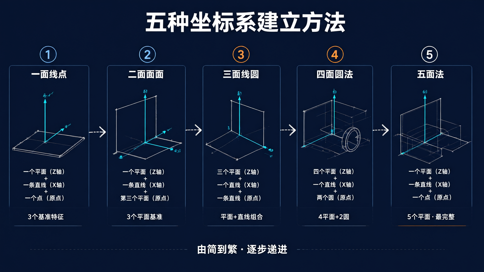
Establishing a coordinate system fundamentally means defining a spatial reference that aligns with the measurement program by using geometric features on the workpiece. Based on different workpiece characteristics, common methods are categorized into five types, progressing from simple to complex.
The one-plane, one-line, one-point method is the most fundamental coordinate system setup. Select a plane on the workpiece to define the Z-axis direction, a line to define the X-axis direction, and a point to set the origin; the Y-axis is then automatically derived using the right-hand rule. This approach is suitable for parts with simple features and clear datums, offering minimal steps but requiring high-quality point selection.
The 2-Plane method determines the Z and X axes using two planes, with a third plane defining the coordinate system's origin. When a workpiece has multiple mutually perpendicular planar datums, this approach fully leverages the part's inherent geometric relationships, resulting in a more stable coordinate system setup.
The three-plane circle method establishes the Z and X axes using three planes, with a line defining the origin. This approach is particularly effective for workpieces featuring both planar and cylindrical surfaces, commonly used in measurements of shaft-like parts.
The Four-Circle Method uses four planes to define the Z and X axes, and two circles to establish the coordinate origin. This method accurately reflects design intent when workpiece datums are primarily circular holes or cylindrical surfaces.
The five-face method is the most complete coordinate system setup approach, establishing a unique coordinate system using five planes. When a workpiece has a complex datum structure, this method fully leverages all available features to minimize the impact of setup errors on measurement results.
Six Degrees of Freedom and Measurement Error
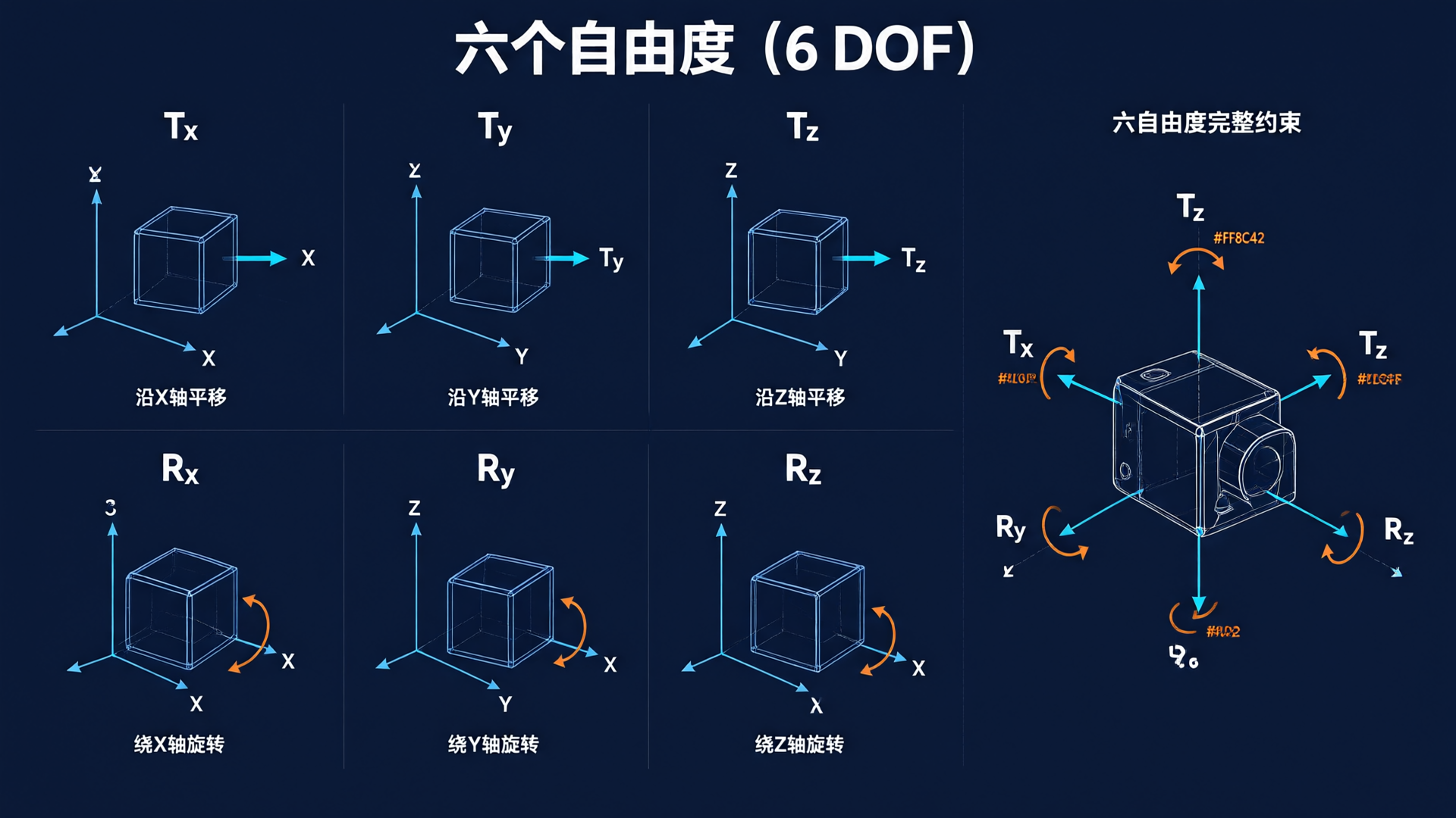
An object in 3D space has six degrees of freedom: translation along the X, Y, and Z axes (Tx, Ty, Tz) and rotation around these three axes (Rx, Ry, Rz). Understanding six degrees of freedom is fundamental to grasping how coordinate systems are established.
Establishing a coordinate system is essentially constraining the six degrees of freedom one by one. Each reference feature defined eliminates one or more degrees of freedom. Once all six degrees of freedom are constrained, the part's position in the measurement space is uniquely determined.
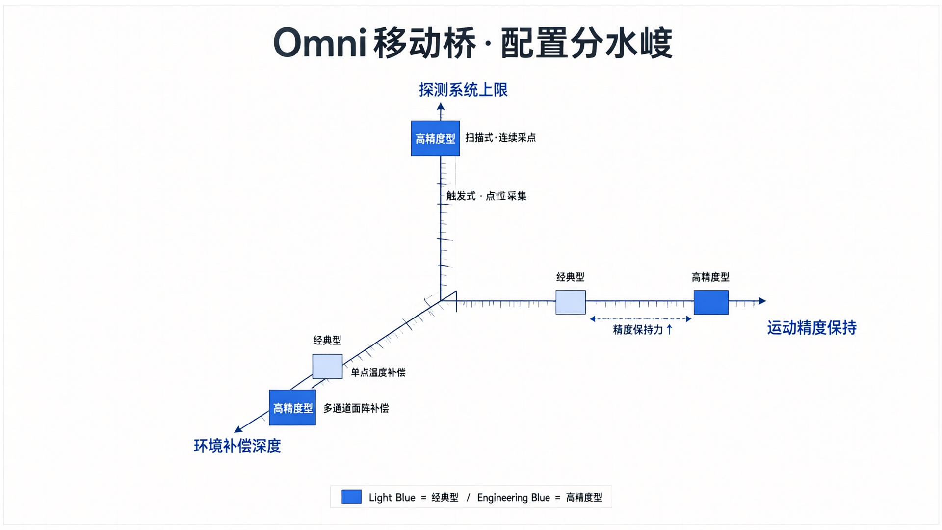
In actual measurements, uncontrolled degrees of freedom are a primary source of error. For example, if the Z-axis is not accurately defined by a planar feature, all vertical dimension measurements will exhibit systematic deviation. The Mico Omni series CMM provides visual feedback during coordinate system setup in its software, enabling operators to verify the constraint status of each degree of freedom in real time.
Rotation and Offset of Coordinate System
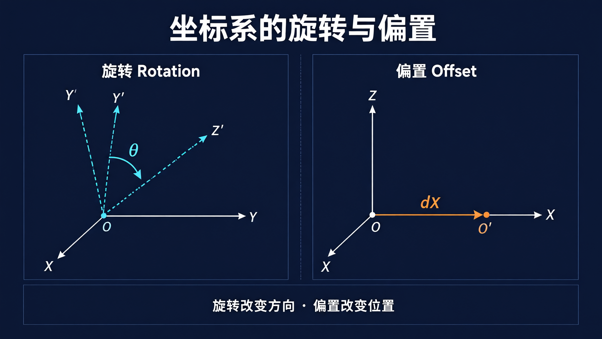
After establishing the coordinate system, you may need to rotate and offset it to align with the reference standards specified in the design drawings.
Rotation refers to rotating a certain angle around an axis to change the coordinate system's orientation. For example, when the workpiece's mounting direction does not align with the measuring machine's default axes, rotation is required to align the measurement coordinate system with the workpiece's design datum. Rotation preserves the origin position and only changes the axis directions.
Offset shifts the coordinate system origin by a specified distance along an axis. It is commonly used to align the origin with the part's design datum, allowing measurement data to directly correspond to dimensioned values on the drawing. Offset changes only the origin position, not the orientation of the axes.
Rotation and offset can be combined to transform the coordinate system from the CMM's default state to the workpiece datum. The accuracy of this process directly ensures consistency between measurement data and design intent.
Impact of coordinate system establishment on measurement results
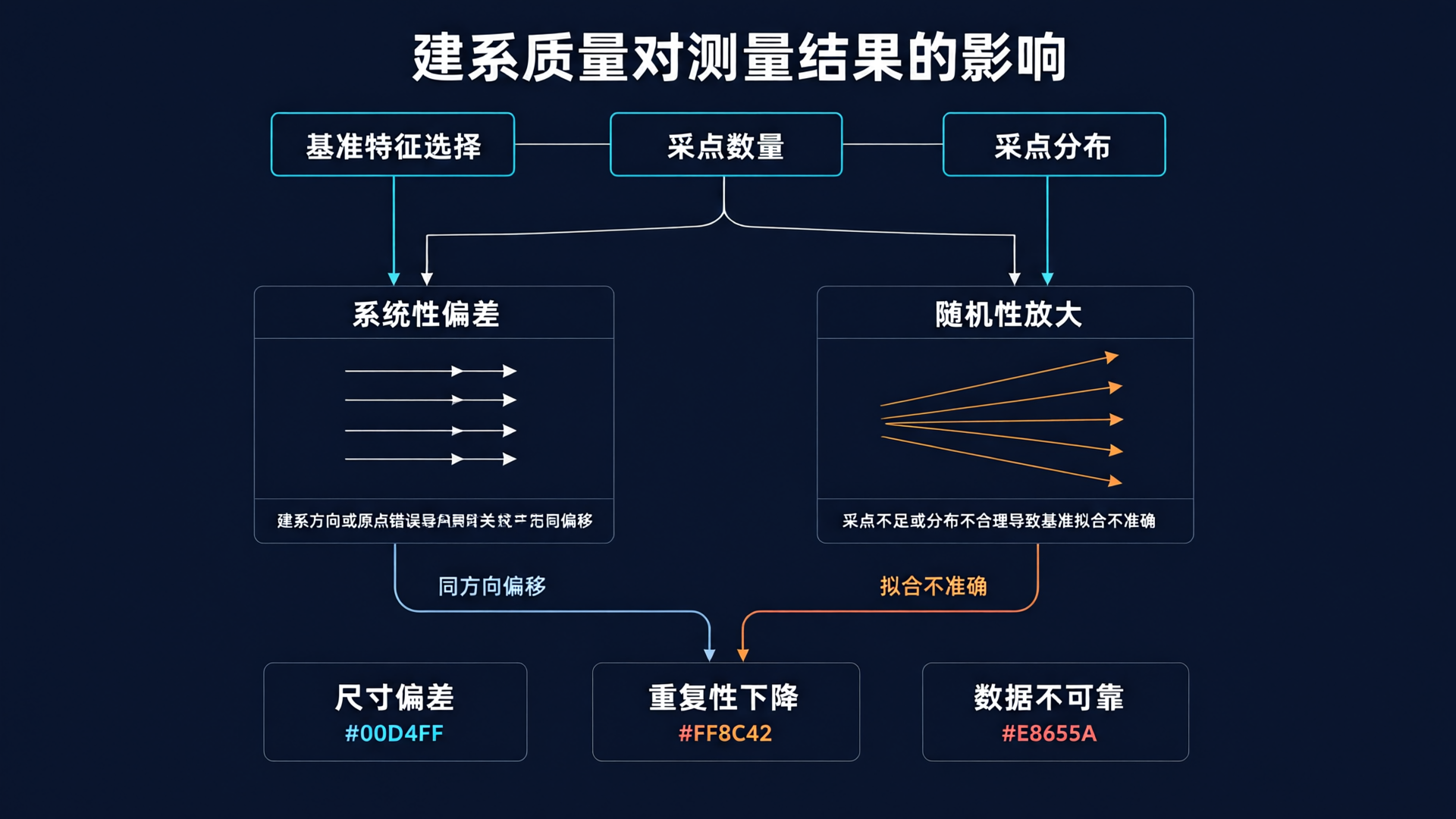
Errors in coordinate system establishment propagate to final measurements in two ways. First, systematic bias: incorrect alignment direction or origin location causes all related dimensions to shift uniformly. Second, random amplification: insufficient point sampling or poor distribution leads to inaccurate fitting of reference features, resulting in unstable coordinate system establishment.
The key to improving coordinate system quality lies in selecting appropriate reference features, ensuring sufficient point sampling, and guaranteeing coverage across the entire feature area. Meike ZhiCe can recommend optimal sampling strategies based on part features, helping operators reduce uncertainty caused by manual judgment.
Establishing a coordinate system is fundamental to surveying. Mastering the applicable scenarios for five coordinate-setting methods, understanding the logic of six-degree-of-freedom constraints, and proficiently using rotation and offset operations collectively form the technical foundation of precision measurement.